ELAN Europe has developed RackNets™, a back-of-rack safety netting system designed to provide better protection against falling loads compared to traditional anti-collapse steel mesh. This system reduces safety risks, offers greater flexibility, and lowers lifetime ownership costs.
Choosing the right RackNets™ solution should be based on a Risk Assessment, particularly when there is a risk of objects falling from height. It should always be used as part of a Safe System of Work to maximise warehouse safety.
RackNets™ 2.3 prevents stock (up to 50kg) from falling from the rear of adjustable pallet racking (APR). It follows the same design principles as the RackNets™ 3.0 and RackNets™ 5.0 systems, however those systems are designed to handle larger loads (up to 1000kg).
Follow the step-by-step guide below to ensure a secure and effective installation of your RackNets 2.3 system.
Stage 1: Fitting Main Brackets
- Each section of safety netting must have a main bracket installed at each of its four corners. Main brackets must be fitted to the top of struts. Some installations may also require intermediate brackets. Always refer to the system drawing supplied to determine the correct bracket placement.
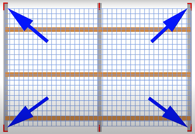
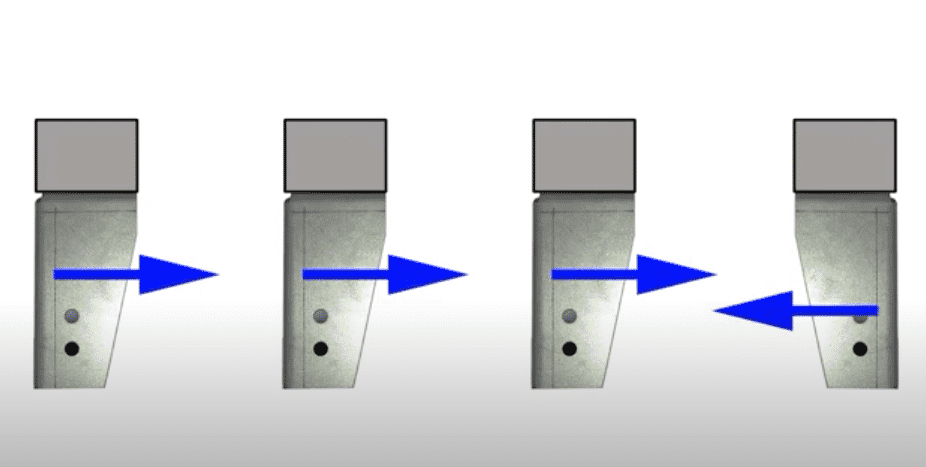
- Main brackets must be installed with the side plate facing in the correct direction to provide additional support and minimise twisting of the uprights (as uprights are designed to take load vertically).
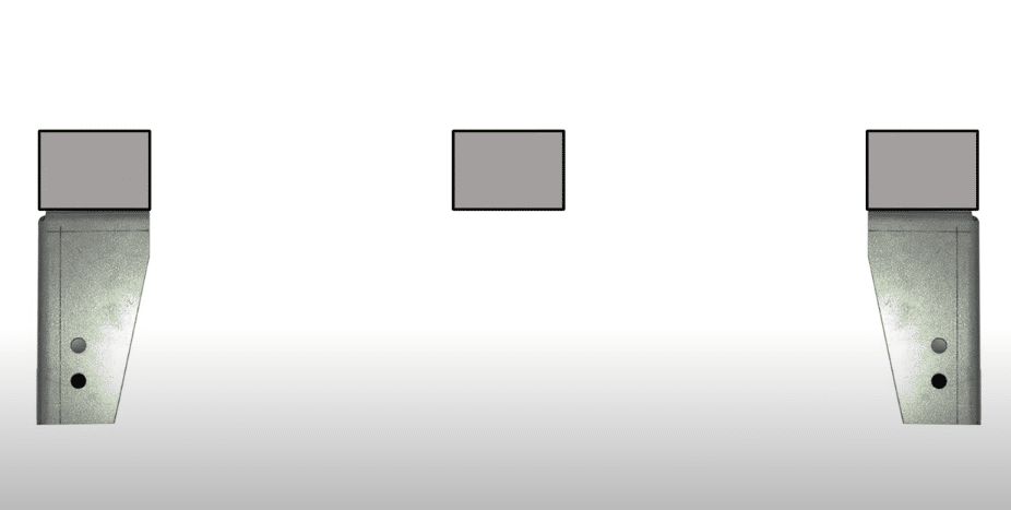
- For a two-bay installation, these are the correct positions:
- For a multi-bay installation, these are the correct positions. Note the position of the bracket facers:
Fixing the Brackets:
- Attach main brackets to the racking struts using two M10 bolts, two M10 nuts, and two M10 washers. Packers should be used as indicated in the supplied installation drawing. All these fittings are the same size for all brackets.
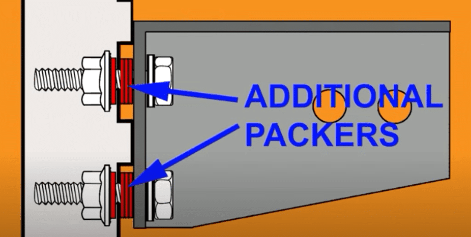
- For apex struts, six additional packers are required to prevent damage to the louvers and support the full width of the bracket:
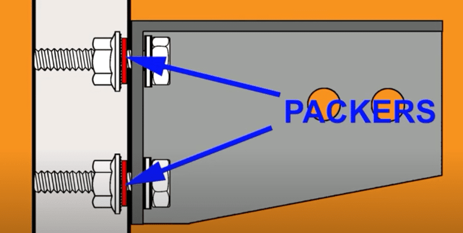
- For non-apex struts, place a packer between the serrated nut and the strut:
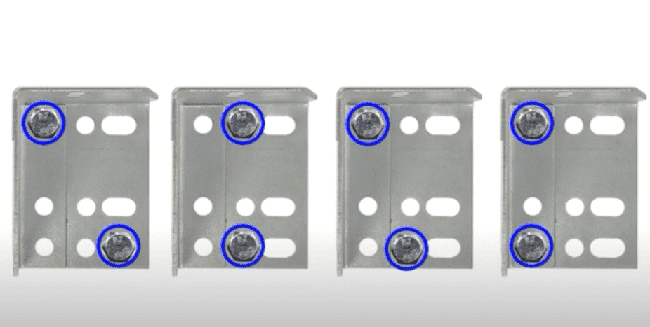
- Main brackets can be fixed to struts using various bolt configurations. All these options are viable and will depend upon the kind of strut you are fixing to:
- Measure down from the centre of the top cable to ensure the bottom brackets are in the right place for the net. This will be detailed on the supplied installation drawing.
Stage 2: Fitting Side and Intermediate Brackets
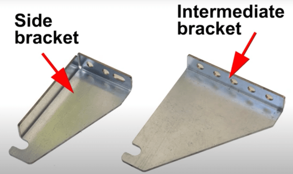
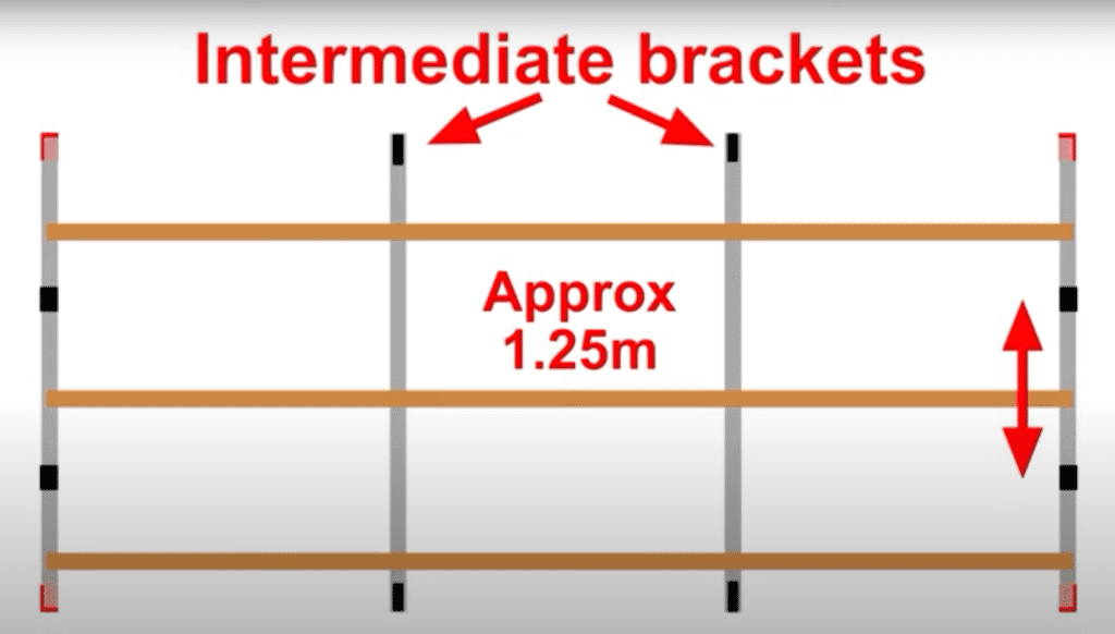
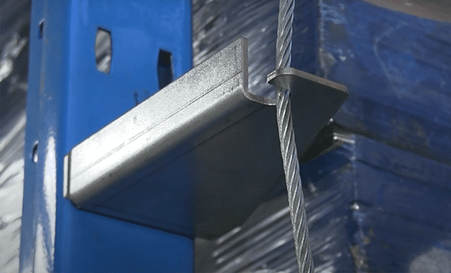
- Side brackets are installed on the end uprights at a spacing of approximately 1.25m to support the vertical cables. The exact spacing may vary depending on beam level locations.
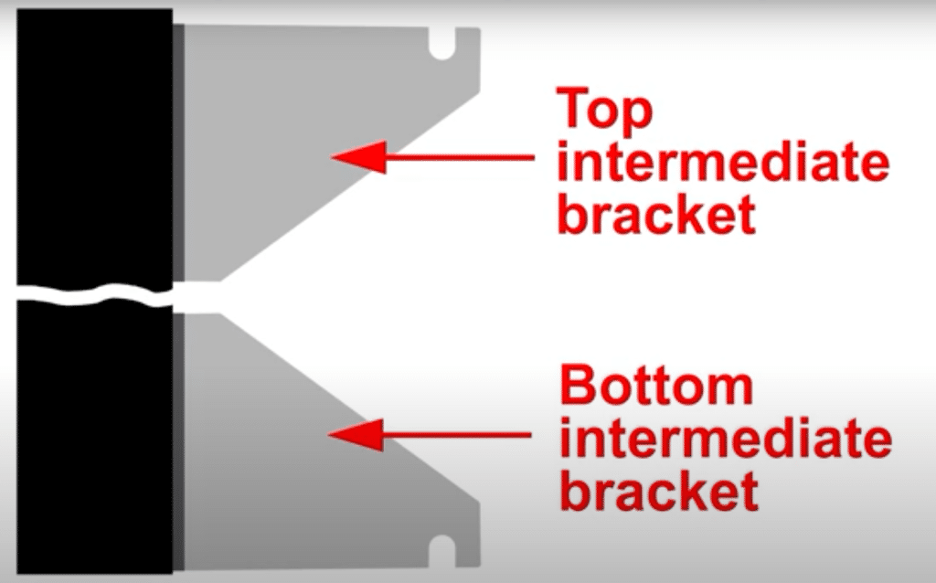
Intermediate brackets must be installed:
- At the top of all vertical struts without a main bracket.
- At the bottom of all vertical struts.
- If there are problems fitting two bolts, side brackets with apex struts can be secured using one bolt. As the raised louvers will prevent rotation, no packers are required.
- This shows the correct fitting for intermediate brackets:
- Apex struts require three packers between the bracket and the shelving upright to prevent damage. Packers should also be fitted to the rear:
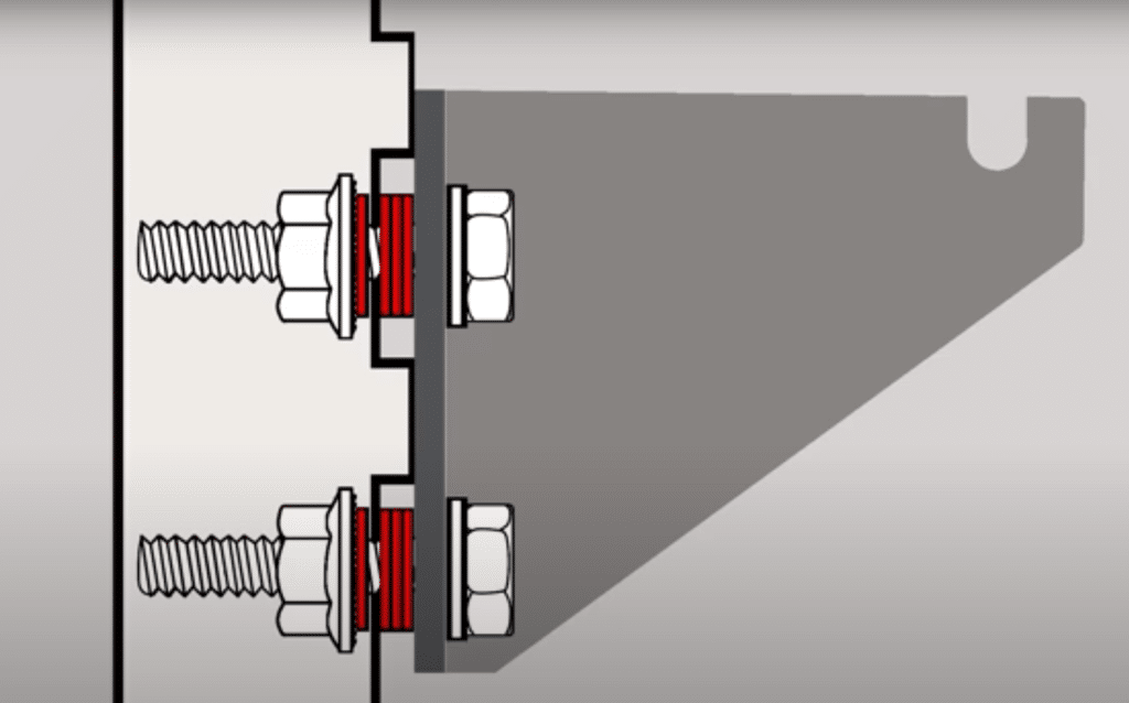
- Non-apex struts require packers only between the nut and the strut. This applies to both the side and intermediate brackets.
- Always refer to the installation drawing and don’t alter the layout without approval from ELAN Europe.
Stage 3: Fitting Horizontal Cables
Cables come in pre-cut and labelled. There is no need to cut any cables. Always check the plans and specification sheets to determine which cable is to be used in which location.
Fixing the Cables:
- Attach the cable to the first main bracket by passing the stud end through the outer vertical hole, and secure it with the supplied locking nut (don’t tighten yet).
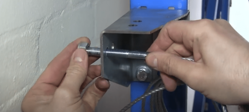
- Thread the cable through any intermediate brackets along the run and through the end main bracket.
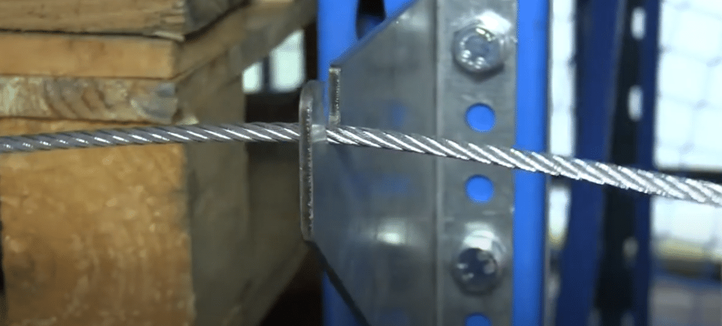
- For single cable installations, pass the cable through one of the holes of the cable fixer, then through one of the holes in the vertical wall of the bracket, then back in through the second hole as shown below, then pass the cable through the second hole of the cable fixer:
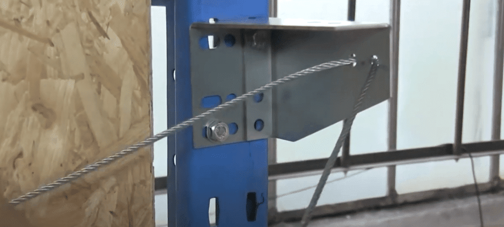
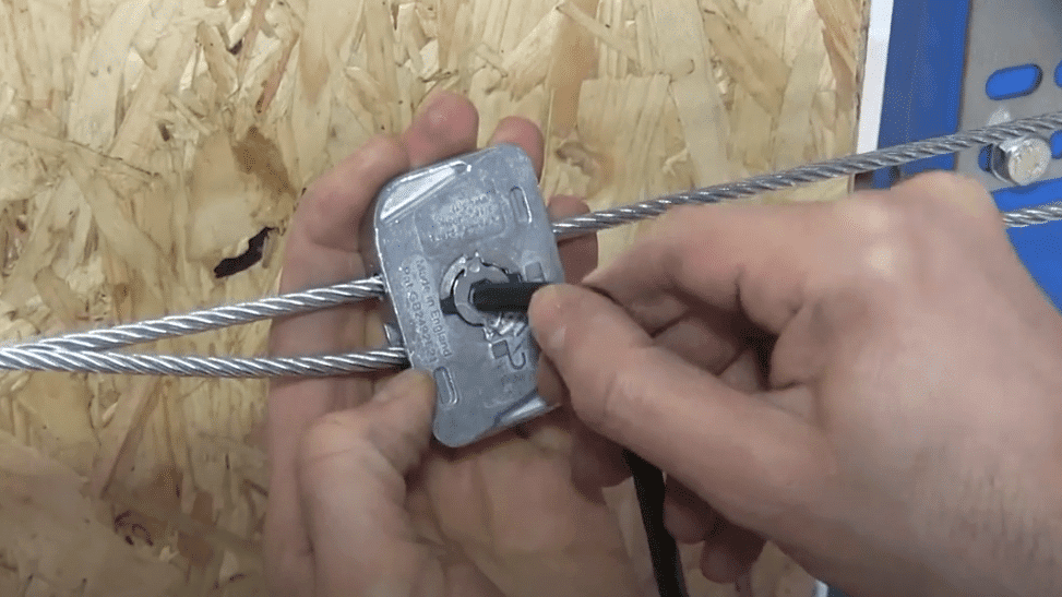
- The cable fixer should be positioned 30-45cm from the bracket.
- Pull the cable hand tight, then lock the cable fixer with an Allen key.
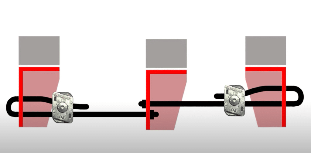
- With two cables on a run, both stud ends will start at a shared central main bracket:
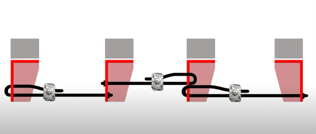
- With three cables on a run, the wires should be fitted like so:
- The cables don’t have to be very tight, as the whole structure takes the strain. Overtensioning of the net can distort the main bracket and may twist the frame.
- Tighten the threaded stud to remove some of the cable sag. Make sure the cable sits level, but is not overtensioned.
- When tensioning multiple cables along a single run, care must be taken to ensure that brackets are only loaded in the permitted direction.
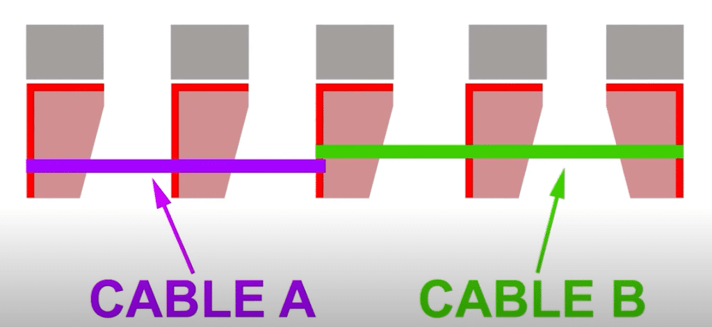
- In this diagram, cable B should be tightened first, as the brackets are facing the right way for maximum strength. Cable A can then be tightened without putting undue pressure on the central bracket, which is the anchor point for 2 cables. Under no circumstances should you attempt to pull an incorrectly fitter bracket straight by over-tensioning the next cable.
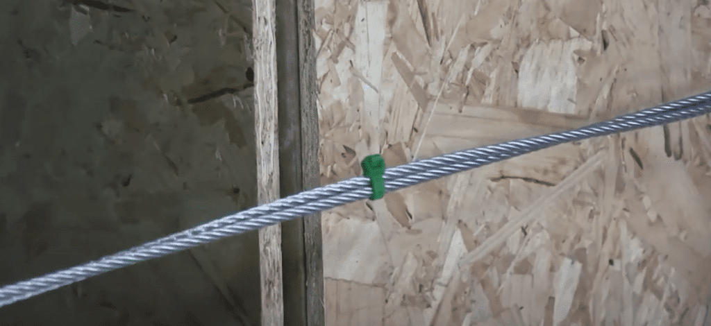
- Tidy any surplus cable using cable ties.
Stage 4: Fitting Vertical Cables
Like the horizontal cables, vertical cables come pre-cut and labelled. Check plans and spec sheets to determine which cables are to be used in which positions.
Fixing the Vertical Cables:
- Fix the cable to the top main bracket by passing the stud end from below into one of the holes.
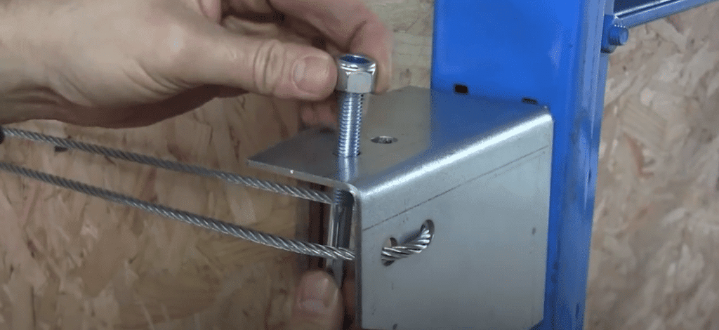
- Fasten the threading stud with a locking nut, but don’t tighten at this stage.
- Thread the cable through any installed side brackets and down to the bottom main bracket.
- Pass the cable through one of the holes of the cable fixer, then through one of the holes in the horizontal plate of the bottom main bracket, then loop it around into the second hole of the bottom main bracket. It then goes back through the second hole in the cable fixer.
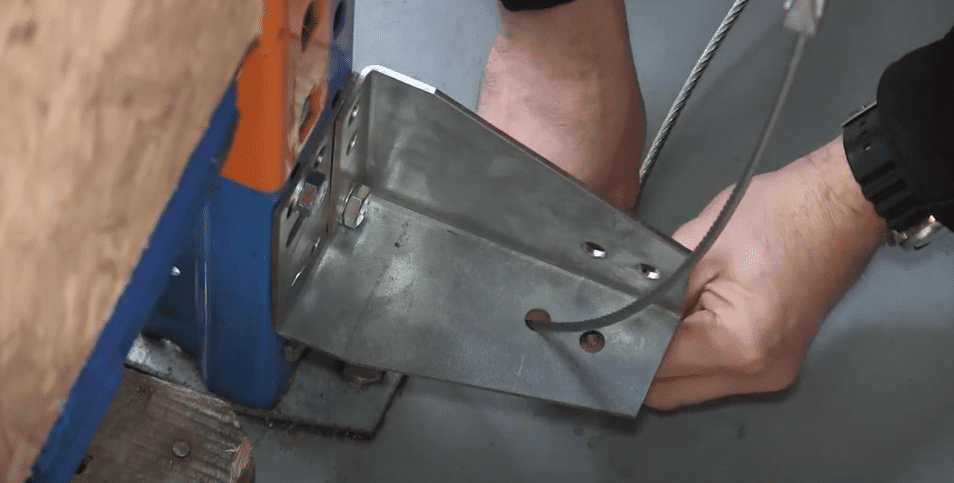
- Make sure the spring inside the cable fixer is flat, this will help the cable to slide through easily.
- The cable fixer should be positioned 30-45cm from the bracket.
- Pull the cable hand tight, then lock the cable fixer with an Allen key.
- The cables don’t have to be very tight, as the whole structure takes the strain. Over-tensioning of the net can distort the main bracket and may twist the frame.
- Tighten the threaded stud to remove some of the cable sag. Make sure the cable sits level, but is not over-tensioned.
- Tidy surplus cable with cable ties.
Stage 5: Fitting Nets
Before fitting, check the label on the net to ensure it’s the correct one. Make sure you identify the width from the height. Nets must be fitted the correct way.
Fixing the Nets:
- Use carabiners to attach the net to the cables.
- Connect carabiners to the outer edge of the net, not the main netting. The outer edge is reinforced to provide more strength.
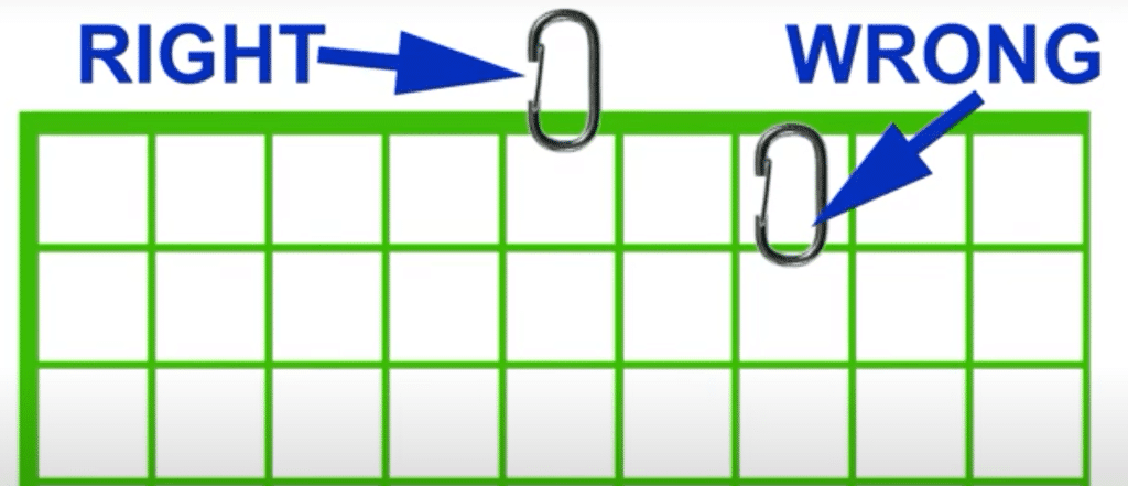
- Fit two carabiners at each corner.
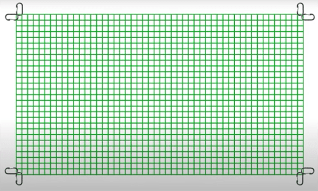
- Attach the next carabiner at 5 net spaces.
- Fit the next one at 6 net spaces, then continue a pattern of 5-6-5-6 and continue until you reach the end.

- You may have a different number of spaces for the last carabiner. Use your judgement to spread the carabiners evenly.
- Fix the carabiners to the rest of the net.
- If an installation is made up of two nets, place carabiners on 3 sides of the first net, and on all four sides of the second net. The middle of each of the two nets will then share one set of carabiners.
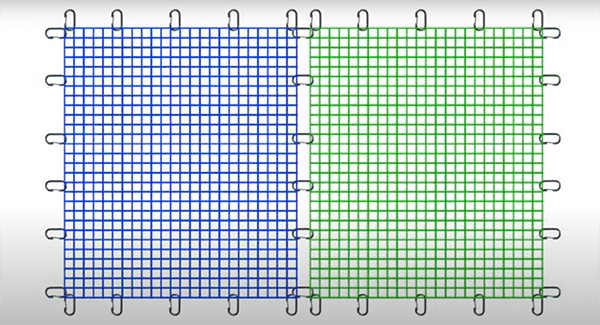
- For an installation with three nets, two nets will have carabiners on 2 sides and the third net will have carabiners on 4 sides. The process is the same for other multi-net installations.
- Attach the two corner carabiners to the vertical and horizontal cables. Connect the top of the net to the top cable. You can connect some of the vertical carabiners while the lift is in the corner position.
- Then fit the two sides, leaving the bottom until last for easier installation.
- On the bottom run, fit the carabiners to the ends first, followed by the centre.
- When the net is in place, make sure the cables pass through all side and intermediate brackets.
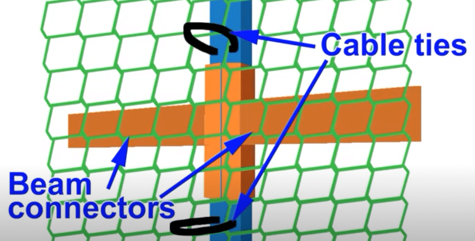
- To support the net, two cable ties are looped around the face of the strut and the net.
The net is not pulled tight against the racking. Cable ties are positioned at each beam connection. One above and one below the connector:
Important:
Shortening nets is required if there’s been an error in the ordering or the racking has been changed in some way.
Do not, under any circumstances, cut the nets. The edges are made to take the strain and are the only part of the net that should be connected to the cables through carabiners.
To shorten a net, fix the carabiners then roll the net, passing the carabiners through the net each revolution. If you need advice on how much a net may be rolled, you should contact installation support for guidance.
End of Installation Guide
By following these instructions carefully, you can ensure optimal safety and functionality for your RackNet system. For any assistance or if you encounter any issues during installation, please contact ELAN Europe for guidance.