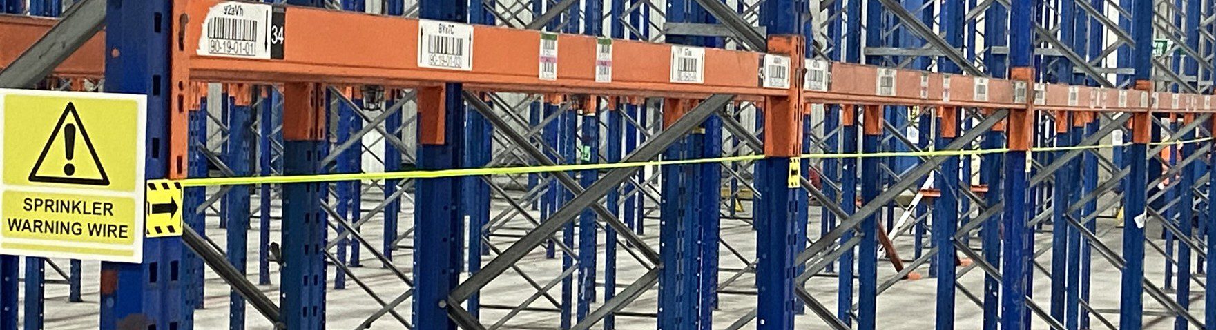
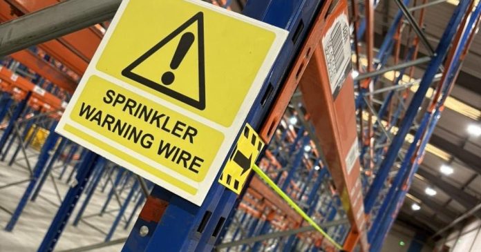
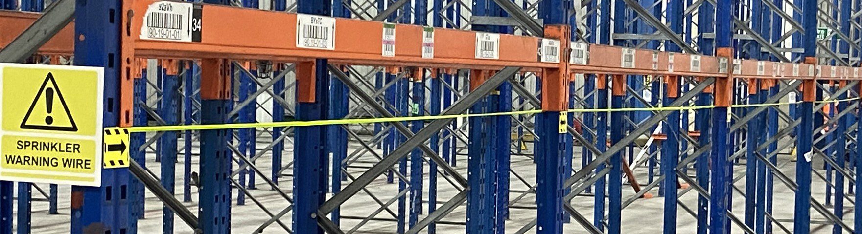
This guide explains how to correctly install the Sprinkler Shield system.
Sprinkler Shield provides:
• Visual guidance for better pallet placement near sprinkler heads
• Physical protection and positive feedback to operator to protect sprinkler heads
Correct installation ensures:
• Proper height alignment to sprinkler head.
• Lightly tension wire.
• Secure fixing at both ends
• No interference with sprinkler operation
Product Overview
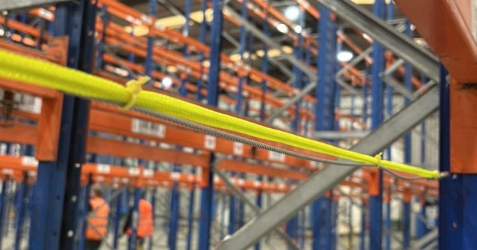
Sprinkler Shield reduces the risk of: • Accidental sprinkler head damage • Water discharge • Loss of storage capacity It is particularly suited to racking systems where sprinklers are: • Not fully protected by flues • Not shielded by rear beams • Installed as face sprinklers The system: • Acts as a visual guide during pallet put-away • Provides physical resistance if contacted • Delivers over 500 kg of push-back resistance under load Installation uses: • 3 mm 7×7 wire rope • 8 mm high-visibility yellow sleeve • Gripple fixing technology • Existing bracing holes in racking uprights
What's Included in Your SprinklerShield Kit
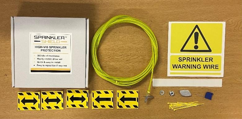
Each kit contains:
3 mm wire rope with either 8 mm stud end or carabiner clip (if the wire end you have does not suit your racking please ring 01925 710923 for support)
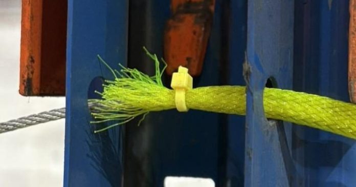
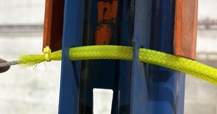
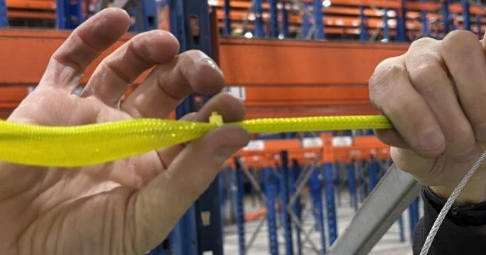
Yellow sleeve (pre-fitted)
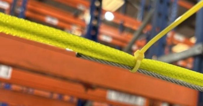
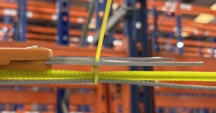
Small yellow cable ties
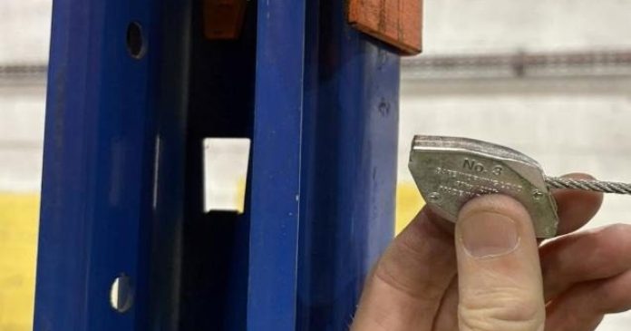
No.3 Gripple release key
8 mm washer
8 mm serrated flange nut
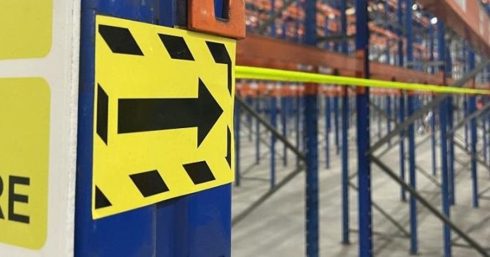
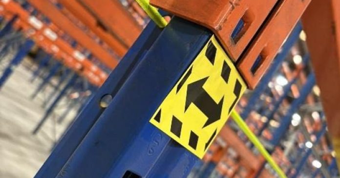
2 single-arrow yellow level labels
3 double-arrow yellow level labels
200 mm rack-end warning sign
Double-sided adhesive pads
Tools and Equipment
Minimum tools:
13 mm spanner (or adjustable spanner)
Pair of reasonable scissors.
Optional: Before starting:
Ensure RAMS and SSOW are in place
Close aisles where required
Follow site-specific working-at-height procedures
Important:
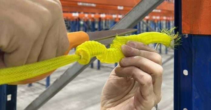
Do not cut the wire rope, as the wire ends are fused to prevent fraying
Cutting will cause fraying
Wear gloves to reduce risk of minor cuts
Take care when leaning into racking
Installation
Pre-installation
Ensure bracing holes are accessible
Confirm stock does not obstruct access
Make sure working area is safe and clear
STEP 1 – UNCOIL THE WIRE
Thread the end back through the coil
Remove twists
Ensure sleeve is straight
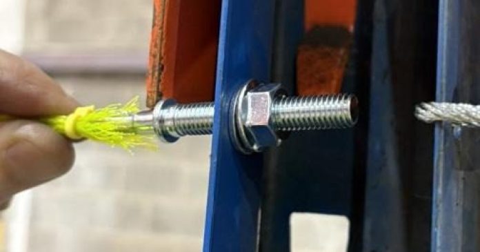
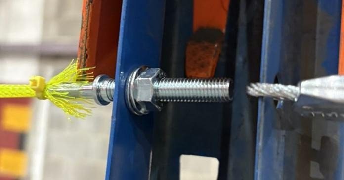
STEP 2 – FIX THE FIRST END (STUD/CARABINER END)
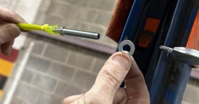
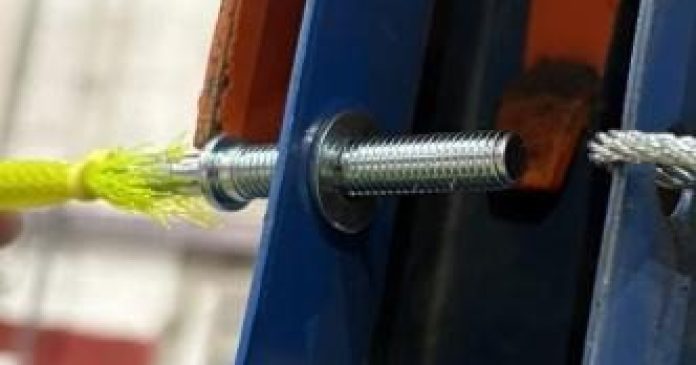
Insert stud through appropriate bracing hole
Fit washer and flange nut
Tighten only one-third to one-half of stud length
You need the thread to tension the wire later.
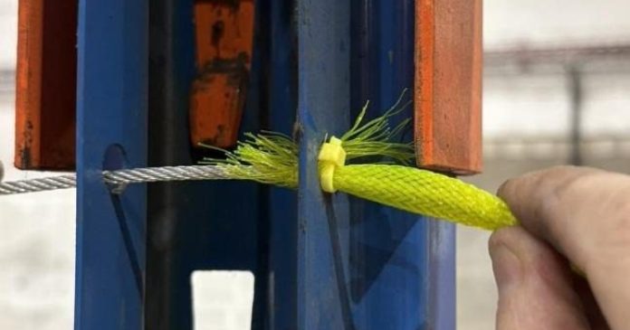
STEP 3 – THREAD THROUGH BAYS
• Move to the next frame
• Pass wire and sleeve through bracing hole
• Repeat across required bays (typically two frames)
• Keep the small yellow cable tie on the sleeve where possible
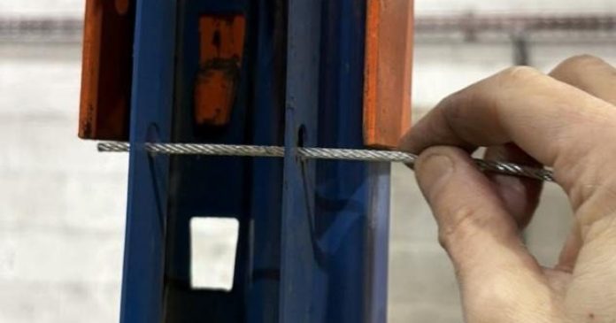
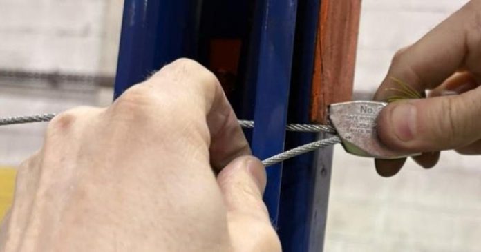
STEP 4 – INSTALL THE GRIPPLE
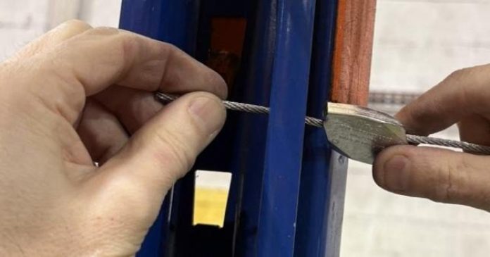
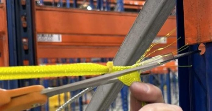
• Slide sleeve back to expose enough bare wire
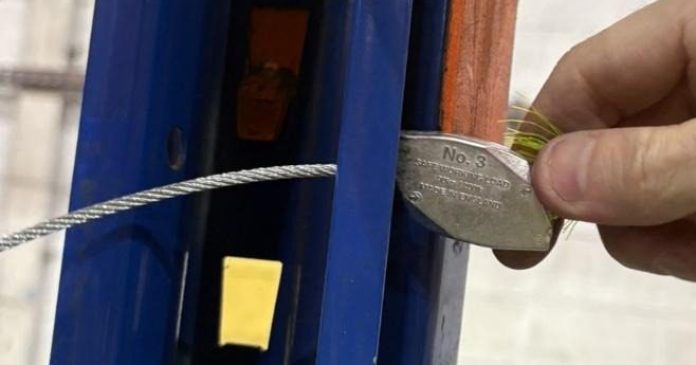
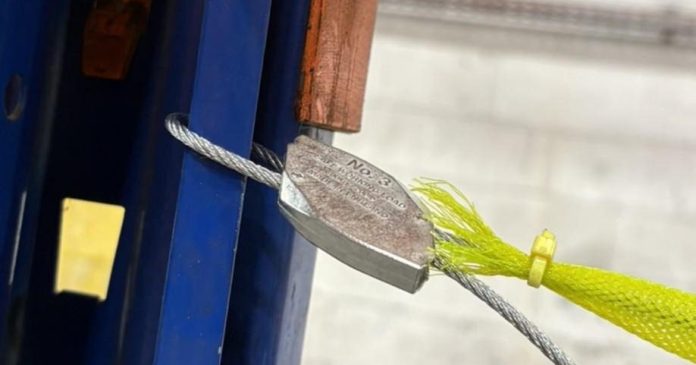
• Position Gripple close to the racking frame
• Thread wire through Gripple where marked with the arrow
• Loop through bracing hole(s)
• Feedback through Gripple
• Pull tail end firmly by hand to apply as much tension as possible by hand. You won’t get it tight at this stage, but as much tension here helps later on.
KEEP THE GRIPPLE LOCK VERY CLOSE TO THE FRAME AT ALL TIMES.
DON’T SLIDE IT DOWN THE WIRE BUT FEED THE WIRE THROUGH INSTEAD
THIS ENSURES YOU DON’T HAVE TO REPOSITION THE GRIPPLE LATER
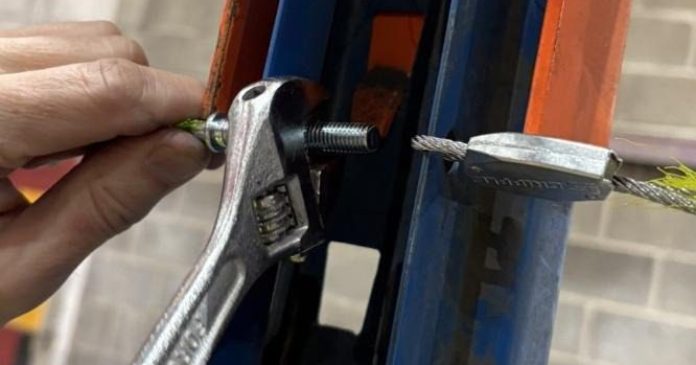
STEP 5 – APPLY TENSION
Return to the stud end
Tighten the flange nut until the wire runs straight across the bays
• Replace the system if the wire becomes severely stretched or damaged
In the Event of an Impact
If struck by a forklift truck: • The wire may stretch • Re-tensioning may not be possible • Replacement may be required
Removal Procedure
1. Loosen the flange nut to release tension 2. Attempt to release the Gripple using the release key but this is normally difficult as the gripple has gripped into the wire marking release difficult.
If release is not possible: Cut the wire between the gripple and the rack frame with wire cutters or snips and remove completely.
Technical Specification
Wire Rope:
• Diameter: 3 mm • Construction: 7×7 • Breaking strain: over 500 kg (see testing document)
Sleeve:
• 8 mm expandable braided PET • Self-extinguishing • Operating temperature range: -50°C to +150°C